 English
  العربية
  日本語
日本語  한국어
한국어  Tiếng Việt
  ไทย
ไทย  Bahasa Melayu
  فارسی
فارسی  Bahasa Indonesia
  ဗမာစာ
ဗမာစာ  简体中文
简体中文  香港中文
香港中文  繁體中文
繁體中文  Русский
  Deutsch
  Nederlands
  Italiano
  Français
  Español
  Português
  Afrikaans
  Azərbaycan dili
  Български
  ਪੰਜਾਬੀ
  हिन्दी
  اردو
اردو  বাংলা
বাংলা  Հայերեն
  Íslenska
  Қазақ тілі
  नेपाली
  Српски језик
  Kiswahili
  తెలుగు
  Basa Jawa
  தமிழ்
தமிழ்  मराठी
मराठी Will Loads Notice an Interruption When a Grid-Tied Energy Storage System Loses Grid Power?
Grid-tied energy storage power outage transfer time
is a waveform.
Whether a load notices grid failure depends on the inverter topology, isolation device, detection logic, and the equipment’s hold-up time.
A distributor commissions a grid-tied battery system, opens the upstream breaker for the acceptance test, and sees the lights stay on. Then the customer’s desktop computer restarts. The battery still has 80% state of charge, so the customer assumes the system failed.
It may have operated exactly as designed. Whether a load notices a grid outage depends mainly on the inverter topology, the transfer device, the detection logic, and the load’s hold-up time. Battery capacity tells you how long backup can run. It does not tell you whether the transition will be seamless.
This article explains the milliseconds that matter and shows procurement teams what to specify before ordering a grid-connected energy storage system.
What Happens Between Grid Loss and Backup Power
A conventional grid-following inverter must stop energizing the circuit when the utility supply disappears. Anti-islanding protection detects abnormal voltage or frequency and disconnects the inverter from the grid. This behavior protects utility workers and complies with interconnection requirements such as IEEE 1547, UL 1741, or local equivalents. A standard grid-tied solar inverter without a backup output cannot power loads during an outage, even at noon with a full battery.
A backup-capable hybrid inverter follows a different sequence. It detects the grid fault, opens an internal or external isolation relay, confirms separation from the utility, and then establishes its own voltage and frequency on the EPS or backup bus. Depending on the hardware and firmware, this process commonly takes 10 to 20 ms. Some products specify less than 10 ms under defined test conditions; contactor-based systems or systems using an external automatic transfer switch may take 20 to 100 ms.
That interval determines what the customer experiences:
The counter-intuitive point is simple: a 20 kWh battery can still allow a 20 ms interruption, while a 1 kWh online UPS can deliver 0 ms transfer. Energy capacity and power continuity solve different engineering problems.
The battery side also has to respond without delay. A typical 51.2 V LFP module uses 16 cells in series, operates around a 44.8 to 57.6 V voltage window, and communicates with the inverter over CAN or RS485. If the inverter requests 5 kW at grid loss, the DC current rises to roughly 98 A before conversion losses. The BMS discharge-current limit, relay state, pre-charge circuit, cable resistance, and cell temperature must all support that step load.
At 25°C, a properly sized LFP pack may deliver 0.5C continuously and reach more than 6,000 cycles to 80% remaining capacity under the manufacturer’s specified depth of discharge. At 0°C, the cells’ internal resistance rises, voltage sag increases, and available discharge power may require derating. A system that transfers cleanly in a warm laboratory can trip on undervoltage in an unheated garage unless the supplier validates low-temperature behavior.
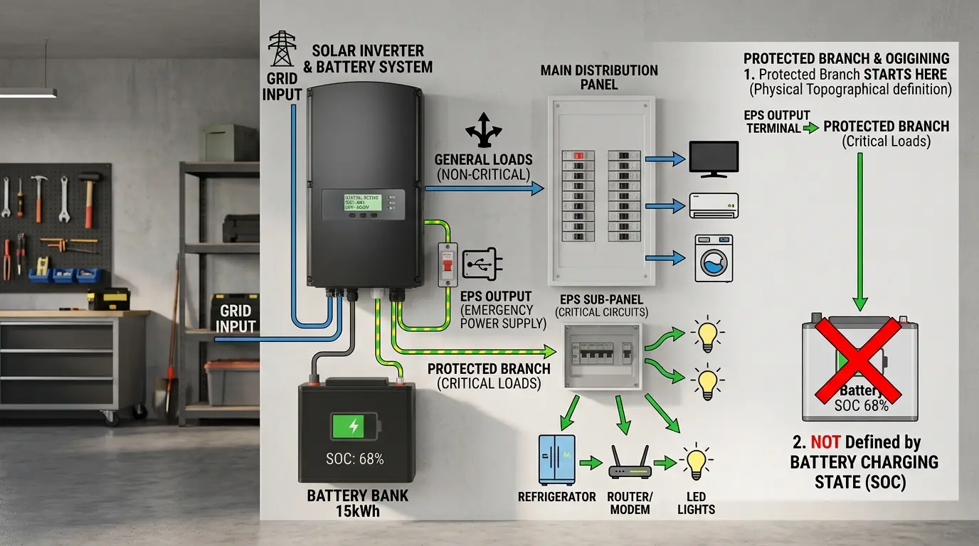
Backup wiring defines the final boundary. Loads connected only to the grid-side main panel will lose power. Only circuits connected downstream of the EPS output or backup gateway receive inverter-formed power after isolation. For whole-home backup, the inverter and switching equipment must carry the expected surge current from pumps, compressors, and motors, not merely the average household demand.
How OEM and ODM Choices Shape Transfer Performance
An OEM or ODM program should lock down backup behavior before label artwork or carton design begins. Ask the factory for a test report that states transfer time, test voltage, load type, load percentage, battery state of charge, and measurement method. “Less than 20 ms” means little if the supplier measured only a resistive load at 30% rated power.
Firmware tuning can adjust grid-loss thresholds, reconnection delays, EPS enable logic, black-start behavior, and battery current ramps within the limits of local grid codes. The inverter and BMS teams must also align CAN message IDs, state-of-charge scaling, alarm mapping, charge and discharge limits, and heartbeat timeouts. A communication mismatch can leave the battery healthy but prevent the inverter from entering backup mode.
White-label buyers can specify regional AC terminals, MC4 or proprietary PV connectors, battery connector families, Wi-Fi or 4G modules, enclosure marking, and language packs. For outdoor installations, confirm the IP rating for the complete assembled system; an IP65 inverter does not make an indoor battery cabinet weatherproof. For transport, require UN38.3 test documentation and matching battery labels for every pack configuration.
Practical programs often begin with engineering samples rather than production units. Agree on the sample lead time, firmware version, communication protocol, and acceptance-load list in the purchase specification. MOQ flexibility matters during certification and pilot deployment, but it should not replace controlled change management. A component substitution in the transfer relay or control board can alter switching performance, so require notification and regression testing.
Which Backup Architecture Fits the Load
| Configuration | Typical transfer behavior | Suitable loads | Main limitation | Procurement check |
|---|---|---|---|---|
| Standard grid-tied inverter without EPS | No backup output | Export and self-consumption only | Loads remain off until the grid returns | Verify that backup is not implied by battery compatibility |
| Hybrid inverter with internal EPS relay | 10–20 ms typical | Lighting, refrigerators, routers, many household circuits | Sensitive electronics may reset | Request oscilloscope traces at 20%, 50%, and 100% load |
| Hybrid inverter with external ATS or backup gateway | 20–100 ms typical, product dependent | Essential-load panels or whole-home backup | Switching time and surge rating depend on external hardware | Confirm ATS transition time, pole configuration, and neutral treatment |
| Online double-conversion UPS paired with ESS | 0 ms at the protected load | Servers, medical devices, process controls | Higher cost, losses, and integration complexity | Check UPS input compatibility with the inverter’s islanded waveform |
Do not select from transfer time alone. Compare continuous EPS power, 10-second surge capacity, phase arrangement, neutral switching, black-start capability, and operation at the lowest specified battery temperature. A 6 kW inverter with a 12 kW surge rating may start a compressor that a nominally larger unit cannot start if that unit limits overload to 110%.
Four Common Pitfalls That Cause Unexpected Outages
Treating the whole building as a backup circuit
Installers sometimes connect the battery inverter for self-consumption but leave all loads on the non-backed-up bus. The monitoring application shows a charged battery, yet every circuit turns off with the grid. Mark the single-line diagram clearly and verify each protected branch during commissioning.
Assuming every sub-20 ms claim behaves like a UPS
Transfer specifications often use resistive test loads. A switched-mode power supply, motor controller, or contactor may respond differently because its current waveform and hold-up time differ. Test representative customer equipment with a power-quality analyzer or oscilloscope. Use an online UPS where a reboot creates safety, data, or production risk.
Ignoring surge current and battery voltage sag
A refrigerator may draw five to seven times its running current during compressor start. If several motors restart together after transfer, the inverter can overload and the 51.2 V battery bus can dip below the BMS cutoff. Sequence large loads, increase parallel battery capacity, or choose an inverter with documented motor-start capability.
Leaving communication and firmware validation until installation
Matching connectors do not guarantee matching protocols. Wrong CAN profiles, outdated firmware, or reversed communication pinouts can force open-loop operation or block discharge. Bench-test the exact inverter, battery, cable, and firmware combination before shipping a container. Record the approved versions in the BOM.
Questions Buyers Ask Before Placing an Order
Will a customer see the lights blink when the grid fails?
Possibly. Many lamps ride through a 10 to 20 ms transfer without a visible interruption, but driver quality and transfer waveform matter. Test the target-market lamp models instead of promising “no flicker” for all lighting.
Can we market a hybrid inverter as providing uninterrupted power?
Only if test evidence supports the claim for the defined loads. A 10 ms or 20 ms EPS transfer is not the same as the 0 ms transfer of an online UPS. State the measured maximum transfer time and identify excluded or sensitive equipment in the installation manual.
How should we test samples before approving mass production?
Test grid loss at low and high state of charge, at several load levels, and with resistive, capacitive, and motor loads. Repeat the test at the minimum operating temperature. Capture AC voltage, AC current, DC bus voltage, and transfer time, then confirm that no BMS or inverter alarm appears.
Does a larger battery eliminate the transfer interruption?
No. More parallel battery modules increase runtime and may improve surge support, but they do not remove the inverter’s detection and isolation interval. Choose the correct power architecture when the load requires 0 ms continuity.
Specification conclusion
A backup-capable energy storage system can keep loads running through a grid outage, but “seamless” depends on the load and the switching architecture. Define the acceptable interruption first. Then verify the inverter’s EPS transfer, the battery’s step-load response, the protected-load wiring, and the complete system under realistic conditions.
Send us your single-line diagram, system voltage, critical-load list, largest motor starting current, and maximum permitted transfer time. We’ll return a preliminary inverter-and-battery BOM plus a sample validation plan within 24 hours.