 English
  العربية
  日本語
日本語  한국어
한국어  Tiếng Việt
  ไทย
ไทย  Bahasa Melayu
  فارسی
فارسی  Bahasa Indonesia
  ဗမာစာ
ဗမာစာ  简体中文
简体中文  香港中文
香港中文  繁體中文
繁體中文  Русский
  Deutsch
  Nederlands
  Italiano
  Français
  Español
  Português
  Afrikaans
  Azərbaycan dili
  Български
  ਪੰਜਾਬੀ
  हिन्दी
  اردو
اردو  বাংলা
বাংলা  Հայերեն
  Íslenska
  Қазақ тілі
  नेपाली
  Српски језик
  Kiswahili
  తెలుగు
  Basa Jawa
  தமிழ்
தமிழ்  मराठी
मराठी OEM / ODM Field Note
All-in-One vs Split Energy Storage Systems for Reliable Field Service
A practical field comparison of integrated and split battery inverter architectures for distributors, wholesalers, installers, and OEM buyers.
under load
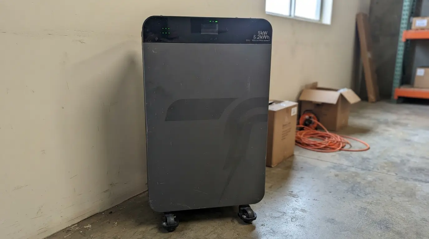
A distributor can install an all-in-one energy storage system quickly, but a fast installation does not automatically produce a serviceable product. When the battery pack, BMS, hybrid inverter, charger, and protection devices share one enclosure, the factory controls more of the integration work. The same concentration can make fault isolation and component replacement harder after the warranty clock starts.
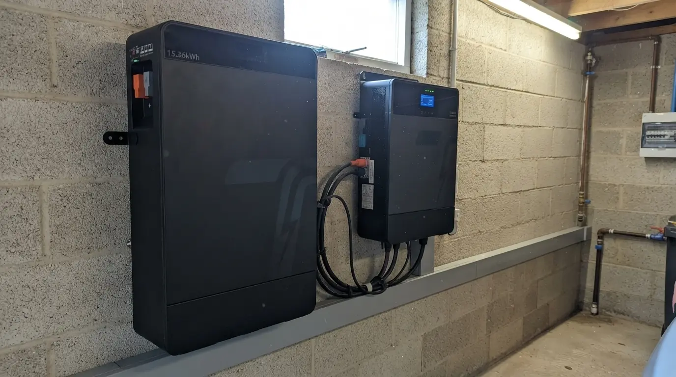
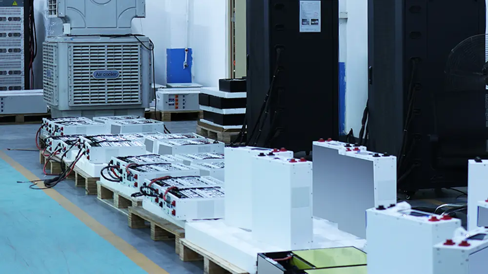
A split system separates the battery and inverter into two service boundaries. It adds DC cabling, communication setup, and more installation checks. In return, a technician can often replace a failed inverter without handling the battery pack, or expand storage without replacing the power-conversion stage.
This comparison gives OEM buyers, wholesalers, and installers a practical way to choose between the two architectures. The answer depends on thermal loading, local service skill, spare-parts policy, communication requirements, and the cost of sending a technician to site.
The Technical Deep-Dive on Reliability and Service Access
Where each architecture reduces failure risk
Reliability starts with the number of interfaces in the system. An all-in-one unit usually leaves the factory with short internal busbars, fixed connectors, a matched BMS-to-inverter protocol, and a completed protection scheme. That reduces field wiring errors such as reversed polarity, loose lugs, incorrect fuse selection, and an RS485 cable connected to the wrong port.
A split system moves some of this risk to installation. A typical 51.2V 100Ah LFP battery stores 5.12kWh and may deliver 100A continuously, while a 5kW inverter can draw roughly 98A from the battery at 51.2V before accounting for conversion losses. The installer must select suitable cable cross-sections, DC isolation, overcurrent protection, and terminal torque. At this current level, a poorly crimped lug can create localized heating that a software alarm will not catch early.
The all-in-one enclosure removes several external high-current connections, but it does not remove heat. A 5kW inverter operating at 94% efficiency produces about 319W of heat at full output. If the battery and inverter share a sealed IP65 enclosure, the mechanical design must move that heat away from the cells and power electronics without allowing moisture or dust into the cabinet. Forced-air fans improve heat transfer but introduce filters, bearings, and service parts. Passive cooling avoids fan failure but may require a larger heat sink and output derating above 45°C.
The battery and inverter do not age in the same way
LFP cells and power semiconductors have different ageing patterns. A well-managed LFP pack can reach 6,000 or more cycles at 80% depth of discharge under a defined test condition such as 25°C and 0.5C. The inverter’s capacitors, relays, fans, and MOSFET or IGBT switching devices respond more strongly to heat, ripple current, load transients, and operating hours.
This difference matters in an all-in-one product. A hot inverter compartment can raise the battery cell temperature even when the cells themselves operate below their maximum discharge current. A BMS may protect the pack by reducing charge or discharge current, but the customer experiences that protection as lower usable power. A split installation lets the integrator place the battery in a cooler location and select a separate inverter with an appropriate thermal path.
Designers should define thermal limits instead of quoting one ambient-temperature number. For example, a system may support 5kW at 25°C, derate to 4kW at 40°C, and limit output further at 45°C. Ask whether the rating applies to the inverter alone, the complete cabinet, or the battery discharge output. Also ask whether the supplier measured the temperature at the cell surface, the BMS MOSFET, or the cabinet air inlet.
BMS communication determines practical reliability
The BMS is the battery’s protection and reporting layer. It measures individual cell voltages, pack current, temperatures, state of charge, and fault status. In a split system, the inverter uses CAN or RS485 data to set charge voltage, charge current, low-voltage cut-off, and restart behavior. A hardwired dry contact may provide a basic emergency stop, but it cannot replace full protocol communication.
An all-in-one system normally ships with the protocol already selected and validated. That helps reduce commissioning time. The buyer still needs the protocol name, baud rate, pinout, termination method, register map, and firmware revision. “CAN compatible” does not tell an installer whether the inverter accepts the battery’s state-of-charge frame or interprets a protection code correctly.
For either architecture, verify these operating points during acceptance testing:
- Cell overvoltage and undervoltage thresholds, including the release delay.
- Continuous and peak discharge current, with the duration for each peak.
- Charge and discharge temperature windows, such as 0°C to 55°C for discharge and 0°C to 45°C for charging, subject to the cell supplier’s limits.
- Passive balancing current, which may be only 50mA to 150mA on a residential pack.
- CAN or RS485 loss behavior, including whether the inverter stops safely or continues on fixed voltage limits.
- Event logs that retain the last fault code after a power cycle.
The OEM and ODM Edge
Architecture decisions affect more than the product enclosure. They determine how a brand handles spare parts, firmware releases, packaging, certification, and field training.
For an all-in-one OEM program, confirm whether the supplier can provide:
- A branded enclosure, nameplate, display language, and startup screen without changing safety labels or mandatory ratings.
- A replaceable inverter module, fan tray, fuse assembly, or control board instead of a sealed replacement-only policy.
- Firmware tuning for the target inverter protocol, peak-shaving logic, generator input, and grid-code settings.
- A service manual showing access sequence, connector identification, torque values, insulation checks, and post-repair commissioning.
- A fault-code export method that a distributor can use without opening the high-voltage or high-current compartment.
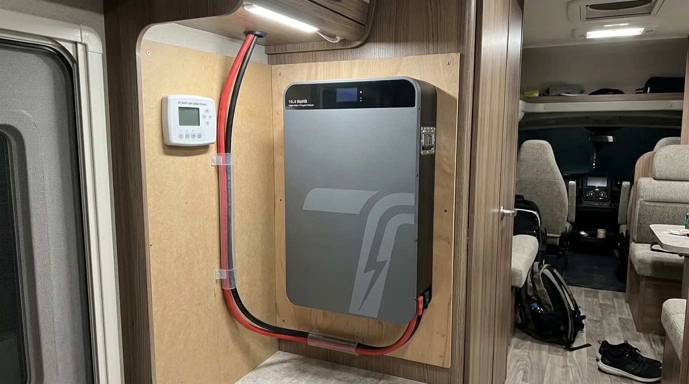
For a split battery OEM or ODM program, the main customization points sit at the battery interface. Specify the terminal format, breaker position, IP rating, CAN and RS485 connectors, cable length, wall-mount or rack-mount hardware, and parallel-battery rules. A 48V rack battery may use a 19-inch rack format, while a wall-mounted unit may need a metal backplate and a separate cable gland area. Both can use the same 16S LFP cell architecture, but their airflow, cable routing, and service access are not interchangeable.
Ask for the MOQ for the first branded batch, the sample lead time, and the firmware change-control process. A realistic sample may take 2 to 4 weeks when the supplier must print labels, build a communication harness, load a custom BMS profile, and complete functional testing. The production lead time should separate cell procurement, assembly, ageing test, and final inspection. That breakdown reveals more than a single promise such as “fast delivery.”
The best OEM partner also defines what the local service team can replace. If a customer in a remote market must ship a 70kg cabinet back to the factory for a $120 control-board fault, the architecture has created a logistics problem. A field-replaceable inverter or communication board may add connectors and a few minutes of assembly, but it can reduce the cost of downtime and reverse logistics across hundreds of installations.
Decision Matrix for All-in-One and Split Configurations
The following comparison uses common residential and light-commercial reference configurations. Treat the figures as procurement benchmarks, not universal product ratings. Final values must come from the cell, inverter, enclosure, and certification test reports for the selected model.
| Configuration | Typical reference size | Reliability strengths | Maintainability strengths | Main service concern | Best fit |
|---|---|---|---|---|---|
| All-in-one wall cabinet | 5kWh to 15kWh, 3kW to 8kW inverter | Factory-matched wiring, fewer external DC joints, validated BMS protocol | One commissioning workflow, fewer field parts | One enclosure fault can remove both storage and conversion; cabinet heat is concentrated | Residential retrofit distributors with trained first-line service |
| Split wall battery plus hybrid inverter | 5kWh to 15kWh battery, 3kW to 8kW inverter | Battery and inverter can use separate thermal locations; independent product replacement | Replace or upgrade inverter without replacing LFP battery | More DC terminals, breakers, cables, and communication checks | Installers with electrical commissioning capability |
| Modular rack battery plus separate inverter | 10kWh to 100kWh or more, 5kW to 30kW system blocks | Parallel modules limit the impact of one battery fault; staged expansion | Hot-swap or module-level replacement is possible when the design supports it | Addressing, current sharing, busbar torque, and firmware compatibility | Small commercial sites and service networks with spare modules |
When comparing supplier quotes, add the service boundary to the spreadsheet. Record whether a failed part means replacing a cell module, BMS board, inverter, complete cabinet, or complete system. Then calculate the delivered replacement cost, technician time, freight, and expected downtime. A lower purchase price can disappear after a few full-unit warranty exchanges.
Four Common Pitfalls
1. Treating an all-in-one cabinet as maintenance-free
An integrated cabinet still contains wear items and inspection points. Fans collect dust, cable glands loosen, surge protective devices age, and firmware can create communication faults after an inverter update. Define a preventive inspection interval, such as every 6 to 12 months, based on dust exposure, humidity, load profile, and local code.
Give the technician a safe isolation sequence. The battery breaker may not remove all stored energy from DC-link capacitors, and a PV input can remain energized in daylight. The service manual must identify the waiting time, voltage verification points, and required PPE. Do not ask a general installer to open a power-electronics compartment without this information.
2. Adding split-system wiring without a commissioning record
Installers sometimes connect the power cables correctly but omit the communications record. Keep the battery address, inverter model, CAN or RS485 pinout, baud rate, termination resistor status, firmware versions, and configured charge limits with the site handover documents.
Check the voltage drop at maximum current. For a 100A 51.2V battery, even a small resistance in the cable path creates measurable loss and heat. Torque each lug to the hardware supplier’s specification, record the result, and inspect for discoloration during the first service visit.
3. Mixing batteries with unverified firmware or state of charge
Parallel batteries need compatible cell counts, charge limits, current-sharing behavior, and communication logic. Do not combine packs simply because both labels say “48V LFP.” Confirm that the BMS firmware supports the target inverter and the planned number of parallel units.
Before parallel commissioning, bring units to a compatible state of charge and follow the supplier’s bus connection sequence. A large voltage difference between packs can create a high equalization current before the inverter even starts. The supplier should state the maximum allowed initial voltage difference and the approved parallel cable layout.
4. Ignoring shipping and service classification
Lithium battery architecture affects packaging and logistics. A system containing a battery pack still needs the applicable UN38.3 test summary, packaging design, labels, documentation, and transport checks. A complete all-in-one cabinet may also have a heavier and less flexible package than a separate battery module and inverter shipment.
Keep the battery and power electronics documentation aligned with the actual shipped configuration. A changed BMS, cell model, enclosure, or battery capacity can trigger a review of transport and market-access documents. Procurement teams should request the exact model’s test summary and dangerous-goods packing instructions before placing a production order.
FAQ
It can be more reliable during installation because the factory controls the internal wiring and communication settings. It is not automatically more reliable over ten years. Compare thermal derating, component-level repair options, fault logs, spare-part availability, and the supplier’s warranty replacement unit before deciding.
An all-in-one system usually needs less installer training at commissioning. A split system can be easier for a mature service network because technicians can replace the inverter or battery independently. Choose the architecture that matches the skills, spare-parts stock, and travel distance of your actual support team.
Yes, when the battery voltage window, charge and discharge current, protection behavior, communication protocol, and certification requirements match. Get a tested inverter profile from the battery OEM or ODM. Do not rely on a generic CAN pinout or a voltage-only control method for a system that requires accurate state-of-charge reporting.
Request the cell datasheet, BMS protection table, inverter efficiency and derating curve, communication protocol, enclosure IP test evidence, UN38.3 documentation, service manual, spare-parts list, sample test report, and warranty failure procedure. Also ask the supplier to demonstrate a BMS communication-loss test and a component replacement procedure on the exact proposed model.
Choose the Architecture Around the Service Model
All-in-one storage works well when a distributor values controlled commissioning, a clean installation, and a single integrated warranty process. Split storage earns its place when the site needs flexible expansion, independent thermal placement, multiple inverter choices, or component-level replacement. Modular rack systems extend that logic for projects where uptime and staged capacity matter more than a small enclosure footprint.
The right question is not which enclosure looks simpler on a quotation sheet. Ask which failure can occur, which part the local technician can replace, how the battery behaves at 40°C, and what evidence proves that the BMS and inverter exchange the correct limits.
Send your target system voltage, daily load curve, peak power, ambient-temperature range, preferred enclosure format, market certifications, and first-batch quantity. We’ll return a preliminary BOM, communication architecture, service-part recommendation, and sample plan within 24 hours.