 English
  العربية
  日本語
日本語  한국어
한국어  Tiếng Việt
  ไทย
ไทย  Bahasa Melayu
  فارسی
فارسی  Bahasa Indonesia
  ဗမာစာ
ဗမာစာ  简体中文
简体中文  香港中文
香港中文  繁體中文
繁體中文  Русский
  Deutsch
  Nederlands
  Italiano
  Français
  Español
  Português
  Afrikaans
  Azərbaycan dili
  Български
  ਪੰਜਾਬੀ
  हिन्दी
  اردو
اردو  বাংলা
বাংলা  Հայերեն
  Íslenska
  Қазақ тілі
  नेपाली
  Српски језик
  Kiswahili
  తెలుగు
  Basa Jawa
  தமிழ்
தமிழ்  मराठी
मराठी Why Low Voltage Cables Heat Up During High Power Discharge
When power rises, current leaves a trace.
A low voltage battery system can deliver serious power. A 5 kW load on a 48 V battery draws about 104 A before inverter losses. The same load on a 24 V system needs roughly 208 A, and a 12 V system needs more than 416 A. That current is the main reason a cable that looks sufficient during light testing becomes hot during a long, high power discharge.
for 5 kW
for 5 kW
for 5 kW
The useful question is not simply whether the cable feels warm. You need to identify where the heat comes from, whether the temperature stays within the cable rating, and whether a loose terminal or undersized conductor is turning a normal loss into a safety problem. The voltage choice itself matters too: see our comparison of 24V and 48V home energy storage systems to understand how system voltage changes current and cable demands.
The Technical Reason Behind Cable Heating
Every cable has electrical resistance. When current flows through it, the cable converts part of the battery’s energy into heat according to P_loss = I²R. Current has a squared effect, so doubling the current creates four times the cable loss if resistance stays unchanged.
For example, assume a 48 V LFP battery uses a 3 m DC cable run with a total circuit resistance of 4 mΩ. At 100 A, the cable pair loses:
100² × 0.004 = 40 WAt 200 A, the loss rises to 160 W. That heat is spread through the conductors, insulation, lugs, and terminals. Bundling, high ambient temperature, limited airflow, and conduit installation make heat rejection harder. Copper resistance also increases as temperature rises, so a hot cable can create further voltage drop and heating. When adding battery modules in parallel, the bank’s higher available current makes conductor sizing and balanced cable runs even more important; review how many 48V low-voltage batteries can be connected in parallel.
The cable may heat for four main reasons:
- The system voltage is low for the required power. A 5 kW inverter draws about 104 A at 48 V, but more than 416 A at 12 V. Higher current requires a larger conductor or shorter run.
- The conductor is undersized or the run is too long. A small cross-section has higher resistance. The positive and negative conductors both contribute to voltage drop and heat.
- A connection has excessive contact resistance. A loose lug, oxidized busbar, incorrect crimp, or terminal tightened below the specified torque can create a hot spot. The cable may remain cool while the lug or fuse holder becomes dangerously hot.
- The installation cannot release heat. Cable trays packed with several DC circuits, direct sun, high ambient temperatures above 40°C, and insulation around the cable reduce the allowable current.
As a practical design reference, a 48 V 100 A battery circuit often uses 25 to 35 mm² copper for a short run, while a 200 A circuit may require 50 to 70 mm² or parallel conductors. The final size depends on cable length, insulation temperature rating, installation method, permissible voltage drop, and local electrical code.
For many inverter applications, keeping DC voltage drop near 2% to 3% helps prevent inverter undervoltage trips and unnecessary battery loss.
What OEM and ODM Buyers Should Specify
Cable heating often begins with an incomplete system specification. When ordering a 48 V wall-mounted or rack battery, give the battery OEM the inverter’s continuous power, peak power, maximum DC current, cable length, ambient temperature, and connector type. A 100 Ah LFP battery with a 100 A BMS cannot safely support a 5 kW inverter at full output just because the battery voltage is nominally 51.2 V.
An OEM or ODM partner can match the discharge harness to the BMS limit, busbar rating, fuse size, and inverter connector. Useful custom options include 25, 35, or 50 mm² cable assemblies, crimped lugs for M8 or M10 terminals, Anderson-style connectors, pre-installed Class-T or MEGA fuses, and CAN or RS485 communication harnesses. Ask for terminal torque values, cable temperature limits, continuous and peak current ratings, and sample test data at 25°C and 40°C.
Cable Choices for the Same 5 kW Load
| Nominal system | Approximate DC current at 5 kW | Typical short-run copper range | Main installation concern |
|---|---|---|---|
| 12 V | 417 A | 95 to 120 mm² or parallel cables | Very high current, large fuses, and severe voltage drop |
| 24 V | 208 A | 50 to 70 mm² | Heat at lugs and busbars during sustained discharge |
| 48 V | 104 A | 25 to 35 mm² | Correct terminal torque and voltage-drop control |
These ranges are starting points, not universal code values. A 10 m circuit, a 50°C equipment room, or a cable installed inside insulation can require a larger conductor. Confirm the ampacity using the cable manufacturer’s table and apply derating factors before final approval.
Four Common Installation Mistakes
- Sizing from battery capacity instead of load current – A 200 Ah label tells you stored energy, not the current that the inverter will draw. Size the cable from continuous and peak current.
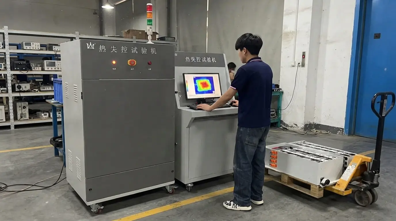
- Checking only the middle of the cable – Use an infrared camera or contact thermometer at the cable, lug, fuse, busbar, and breaker after a sustained load. A terminal that is much hotter than the conductor points to contact resistance.
- Ignoring the complete circuit length – Calculate the round-trip length of positive and negative conductors. A 3 m one-way route is a 6 m current path.
- Skipping torque and crimp checks – Follow the battery manufacturer’s torque specification, often around 8 to 12 N·m for M8 power terminals. Use the correct crimp die and pull-test the lug on production assemblies.
FAQ
Is it normal for a battery cable to feel warm?
Some temperature rise is normal under high current, but the permitted value depends on the insulation and installation method. A cable that becomes too hot to touch, softens its insulation, smells, or shows discoloration needs immediate shutdown and inspection. Compare the measured temperature with the cable and equipment ratings rather than relying on touch alone.
Why does the terminal heat up while the cable stays relatively cool?
The terminal probably has higher resistance than the conductor. Check for loose hardware, a poor crimp, corrosion, a mismatched lug, or a damaged busbar. Do not solve this condition by simply installing a larger cable.
Will raising the battery voltage reduce cable heating?
Yes, for the same power. Moving a 5 kW load from 24 V to 48 V approximately halves the current, and the theoretical resistive loss falls to about one quarter. The battery, inverter, fuse, and BMS must all support the higher voltage class.
Conclusion
Low voltage cables heat during high power discharge because current creates resistive loss, and low voltage systems need more current to deliver the same power. Select the conductor from the real current, route length, ambient temperature, installation method, and voltage-drop target. Then inspect every connection under load, because a hot lug can signal a more urgent fault than a warm cable.
Share your system voltage, inverter power, peak current, cable length, and installation temperature with an OEM or ODM engineering team. They can return a preliminary cable, fuse, terminal, and BMS specification for your project within 24 hours.