 English
  العربية
  日本語
日本語  한국어
한국어  Tiếng Việt
  ไทย
ไทย  Bahasa Melayu
  فارسی
فارسی  Bahasa Indonesia
  ဗမာစာ
ဗမာစာ  简体中文
简体中文  香港中文
香港中文  繁體中文
繁體中文  Русский
  Deutsch
  Nederlands
  Italiano
  Français
  Español
  Português
  Afrikaans
  Azərbaycan dili
  Български
  ਪੰਜਾਬੀ
  हिन्दी
  اردو
اردو  বাংলা
বাংলা  Հայերեն
  Íslenska
  Қазақ тілі
  नेपाली
  Српски језик
  Kiswahili
  తెలుగు
  Basa Jawa
  தமிழ்
தமிழ்  मराठी
मराठी What Discharge Cutoff Voltage Protects a Battery Pack Without Damaging the Cells
The useful cutoff is not the lowest number a BMS can tolerate. It is the operating boundary that leaves the weakest cell enough room to stay healthy.
Setting the discharge cutoff too high leaves usable energy in the pack. Setting it too low can push the weakest cell into over-discharge, even when the total pack voltage still looks acceptable.
The practical answer depends on the cell chemistry, the number of cells in series, discharge current, and temperature. For most lithium battery systems, the inverter or load should stop the discharge before the BMS reaches its emergency protection limit. For more on residential battery sizing and usable energy, see our guide to choosing the right home energy storage capacity.
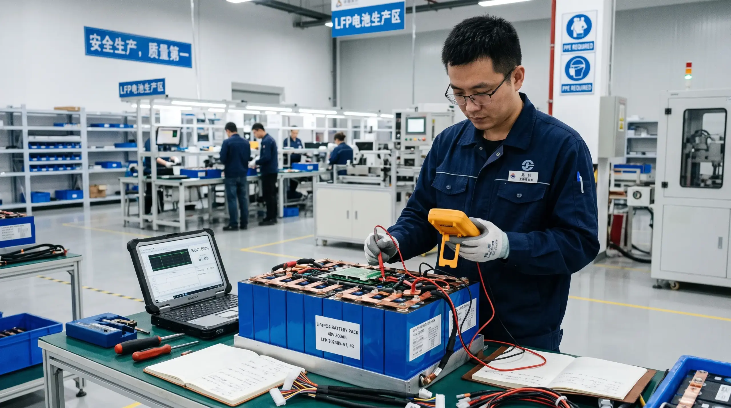 Battery pack inspection image
The Safe Voltage Window Depends on Cell Chemistry
For a lithium iron phosphate battery, or LFP, a good daily cutoff is usually around 2.9 to 3.0 V per cell under load. A 16S 51.2 V LFP battery therefore commonly uses an inverter low-voltage disconnect around 46.4 to 48.0 V. The exact value should follow the cell supplier’s discharge curve and the battery manufacturer’s BMS settings. For a real-world 51.2V reference, review the specifications of TURSAN’s 48V 100Ah LiFePO4 home backup battery.
The BMS may allow a lower emergency cutoff, often close to 2.5 to 2.7 V per cell, but that is a protection boundary, not a healthy operating target. Repeatedly reaching it increases stress on the lowest-voltage cell and can make the pack fall out of balance faster. Because usable energy and cycle life also depend on depth of discharge, use the depth-of-discharge and cycle-life calculator to compare operating windows.
Voltage sag also matters. At a high discharge rate, a pack may briefly fall below the inverter cutoff even though its resting voltage remains higher. That is why a reliable design checks both voltage and current, and why the BMS monitors each cell rather than only the total pack voltage. Estimate current at the intended discharge rate with the site’s battery C-rate to current calculator.
 Voltage testing image
Practical LFP Cutoff Examples
| Battery configuration | Daily inverter cutoff | BMS emergency range | Typical use |
|---|---|---|---|
| 4S 12.8 V LFP | 11.6–12.0 V | 10.0–10.8 V | Small backup packs and portable systems |
| 8S 25.6 V LFP | 23.2–24.0 V | 20.0–21.6 V | RV, telecom, and light off-grid loads |
| 16S 51.2 V LFP | 46.4–48.0 V | 40.0–43.2 V | Home storage and rack battery systems |
These are practical starting points, not universal specifications. A pack with a conservative BMS, long cable runs, or high peak loads may need a higher inverter cutoff to avoid nuisance trips and deep cycling.
Do Not Treat Pack Voltage as Cell Voltage
A battery pack can show a normal total voltage while one weak cell has already reached its lower limit. For example, one cell in a 16S LFP pack may drop sharply under load while the other 15 cells remain stable. The total voltage can still appear acceptable to the inverter.
This is the main reason a battery should include cell-level monitoring, passive or active balancing, and a BMS that records the lowest cell voltage. The inverter protects the pack at the system level. The BMS protects individual cells at the electrical limit.
Temperature changes the answer as well. Cold cells show more voltage sag and deliver less usable capacity. At temperatures near or below 0°C, charging restrictions become especially important. The discharge cutoff should be tested at the lowest operating temperature and the highest expected load, not only at 25°C and a light test current. See also how depth of discharge affects battery warranty and cycle life.
 Rack battery system image
The OEM and ODM Settings That Matter
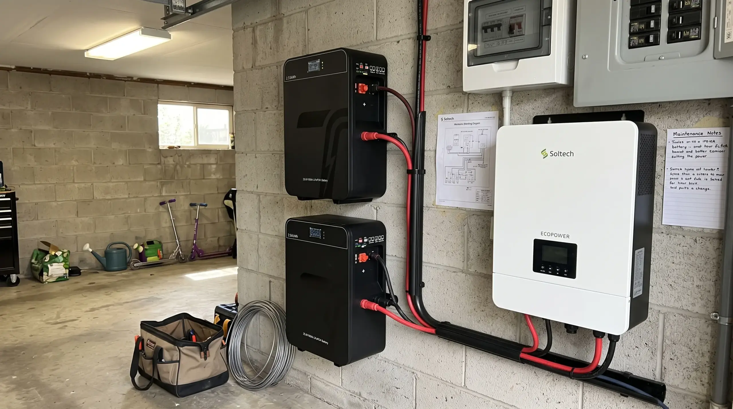
For an OEM or ODM battery project, the cutoff voltage should be agreed together with the current limit, cell model, and communication protocol. A 51.2 V rack battery may need different firmware when paired with a 3 kW inverter than when paired with an 8 kW inverter. TURSAN’s OEM and ODM customization service covers project-specific battery configurations and system integration.
Useful customization points include:
- Inverter low-voltage disconnect and restart thresholds
- BMS cell over-discharge warning and protection values
- CAN or RS485 voltage and state-of-charge mapping
- Connector, fuse, and cable sizing for the target current
- Label branding, enclosure format, and sample firmware before mass production
Ask the supplier for a discharge curve at the intended C-rate, the lowest-cell protection setting, and the recovery voltage after a cutoff event. Those details are more useful than a single nominal voltage printed on the datasheet.
Four Common Cutoff Mistakes
- Copying a 12 V setting into a 48 V system – Multiply the per-cell target by the actual series count. Do not scale from nominal labels alone.
- Using the BMS emergency limit as the daily cutoff – This consumes the safety margin and increases the chance of a hard shutdown.
- Ignoring voltage sag – A high-power inverter can pull the pack below its threshold for a few seconds. Check cable resistance, terminal torque, and peak current before lowering the cutoff.
- Mixing chemistries or firmware profiles – LFP, NMC, and lead-acid batteries need different voltage windows. The inverter profile must match the installed chemistry and series count.
FAQ
Conclusion
For a typical 16S 51.2 V LFP battery, 46.4 to 48.0 V is a sensible daily discharge cutoff range, while the lower BMS limit should remain an emergency safeguard. Always verify the per-cell setting, series count, load current, and temperature before finalizing the inverter profile.
Send your cell chemistry, series count, inverter model, and peak load current to an OEM battery team, and they can return a preliminary cutoff profile and BMS communication map before sampling.