 English
  العربية
  日本語
日本語  한국어
한국어  Tiếng Việt
  ไทย
ไทย  Bahasa Melayu
  فارسی
فارسی  Bahasa Indonesia
  ဗမာစာ
ဗမာစာ  简体中文
简体中文  香港中文
香港中文  繁體中文
繁體中文  Русский
  Deutsch
  Nederlands
  Italiano
  Français
  Español
  Português
  Afrikaans
  Azərbaycan dili
  Български
  ਪੰਜਾਬੀ
  हिन्दी
  اردو
اردو  বাংলা
বাংলা  Հայերեն
  Íslenska
  Қазақ тілі
  नेपाली
  Српски језик
  Kiswahili
  తెలుగు
  Basa Jawa
  தமிழ்
தமிழ்  मराठी
मराठी How Much Usable Capacity Does a 100Ah LiFePO4 Battery Pack Really Have
A 100Ah label answers only one part of a battery question. It tells you the charge quantity measured under a defined test condition, not the exact energy your load will receive in the field. A 12V 100Ah LiFePO4 battery can deliver noticeably less than its nameplate figure when the system reserves capacity, the temperature falls, or an inverter converts the DC power to AC.
FIELD ESTIMATE / TYPICAL 12.8V PACK / 25°C
For a typical 12.8V pack, the quick calculation is 12.8V x 100Ah = 1,280Wh, or 1.28kWh of nominal energy. In normal operation, expect roughly 1.0 to 1.15kWh of usable DC energy, depending on the battery management system and the selected depth of discharge. This article shows how to calculate the number for a real installation.
Start With Nominal Energy
Use the battery’s nominal voltage rather than its maximum charging voltage:
Nominal energy = nominal voltage x rated capacity
For a 12.8V LiFePO4 pack:
12.8V x 100Ah = 1,280Wh
The same 100Ah capacity produces different nominal energy at different voltage levels. A 25.6V pack stores about 2.56kWh, while a 51.2V pack stores about 5.12kWh. The amp-hour figure stays at 100Ah, but the voltage changes the energy available to the load.
The pack’s BMS also keeps a small reserve at the top and bottom of the cell voltage window. That reserve protects the cells from overcharge and over-discharge. A pack rated for 100Ah at 0.2C and 25°C may not provide the same result at 1C, -10°C, or after years of cycling.
What You Can Actually Use
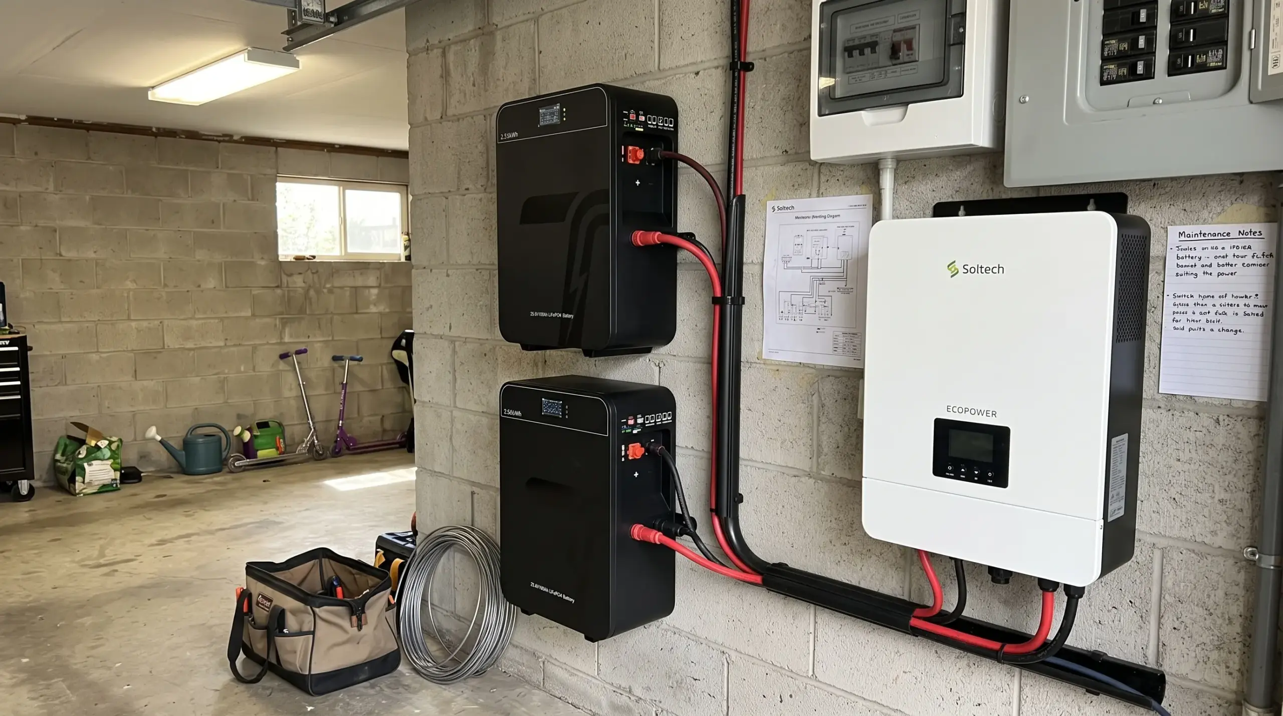
Depth of discharge, or DoD, gives the clearest first adjustment. If the system allows 90% DoD, the theoretical DC energy becomes:
1,280Wh x 90% = 1,152Wh
At 80% DoD, it becomes 1,024Wh. If an off-grid inverter operates at 92% efficiency, an 80% DoD calculation gives approximately 942Wh of AC energy before cable losses and low-voltage cut-off effects. This is why a buyer should not size a load from the 1.28kWh nameplate alone.
The following figures use a 12.8V 100Ah pack at 25°C. They are planning values, not a substitute for the manufacturer’s discharge curve.
A Practical Capacity Comparison
| Operating assumption | Usable DC energy | Approximate AC energy at 92% inverter efficiency | Suitable planning use |
|---|---|---|---|
| 100% theoretical nameplate | 1,280Wh | 1,178Wh | Datasheet comparison only |
| 90% DoD | 1,152Wh | 1,059Wh | Daily solar storage with a conservative reserve |
| 80% DoD | 1,024Wh | 942Wh | Longer cycle-life planning |
| 80% DoD at 0.5C load | About 980Wh | About 900Wh | Typical mixed household or light commercial loads |
The 0.5C row assumes a 50A discharge from the 100Ah pack and recognizes that voltage sag and conversion losses reduce delivered energy. A pack with a 100A continuous rating can support higher power, but that does not mean it will deliver the same watt-hours as a gentle 20A test.
Four Factors That Reduce Delivered Capacity
- Discharge currentCell capacity tests often use 0.2C, which equals 20A for a 100Ah pack. A 1C discharge draws 100A and creates more voltage sag and heat. The BMS may disconnect the pack early if the weakest cell reaches its low-voltage limit.
- TemperatureLiFePO4 batteries generally deliver their best capacity near 20 to 30°C. At 0°C, available capacity can fall, and the BMS should block charging unless the pack includes low-temperature protection or heating. Review the guidance on charging LiFePO4 batteries in cold conditions, then request the supplier’s discharge data at the intended operating temperature.
- Reserve settingsA hybrid inverter may stop discharge at a 10% or 20% state-of-charge setting. The BMS may apply a separate low-voltage cut-off. The higher cut-off wins, so the usable window can be smaller than the value shown in the inverter app.
- Conversion and wiring lossAn AC load receives less energy than the battery produces on the DC side. A 92% efficient inverter, 2% cable loss, and standby consumption can reduce 1,024Wh of battery-side energy to around 920Wh at the appliance.
The OEM and ODM Design Difference
For distributors and system integrators, the rated 100Ah figure should match a stated test method. An OEM supplier can specify whether the capacity test uses 0.2C, 25°C, a 2.5V-per-cell cut-off, or another endpoint. Ask for the discharge curve, BMS low-voltage threshold, continuous current rating, and capacity tolerance before approving a private-label datasheet.
An ODM project can also tune the usable window for the application. Firmware may reserve more energy for cycle life, change the CAN or RS485 state-of-charge map, or coordinate the pack with a particular inverter. The enclosure, terminal layout, connector, label, and UN38.3 shipping documentation should match the final system rather than a generic catalog sample.

Four Common Planning Mistakes
- Multiplying 100Ah by 12V and treating 1,200Wh as guaranteed outputUse the actual nominal voltage, then apply DoD and system efficiency.
- Using the maximum charge voltage as the average discharge voltageA 12.8V pack may charge to about 14.2 to 14.6V, but its nominal energy calculation uses 12.8V.
- Ignoring the load profileA refrigerator compressor, pump, or inverter may create a high startup current even when its average wattage looks small. Check both continuous and peak current limits.
- Comparing capacity figures with different test conditionsA 100Ah rating at 0.2C and 25°C is not directly comparable with a 100Ah rating measured at 1C or at a low temperature. Put the test conditions beside every capacity value in a procurement sheet.
FAQ
Question: Can a 100Ah LiFePO4 battery run a 1,000W load for one hour
Question: Is 80% DoD better than 100% DoD
Question: Does a 100Ah pack always contain 1.28kWh
The Engineering Answer
A 12.8V 100Ah LiFePO4 pack has a nominal capacity of 1.28kWh, but a realistic planning figure is usually about 1.0 to 1.15kWh on the DC side. After a 92% inverter and normal cable losses, the connected AC load may receive roughly 0.9 to 1.05kWh. Use the supplier’s discharge curve when the load is large, the temperature is low, or the battery will operate near its current limit.
For an OEM or ODM quotation, send the system voltage, continuous and peak load, target DoD, operating temperature, and inverter model. Those five inputs allow a supplier to return a usable-capacity calculation and a preliminary BOM rather than a nominal amp-hour promise.